This article describes how to simulate VLAN ID's in your home lab without the need for a physical switch and how to create a bridge between a VLAN in GNS3 and a segment in NSX-T. GNS3 is a great free product that's able to simulate routers and switches.
This simulation is done by hosting the original binaries on a network virtualization platform. The GNS3-VM can run as a virtual machine hosted on ESXi. The user-interface of GNS3 is a separate client that runs on your workstation but the network virtualization is done in the GNS3-VM virtual machine.
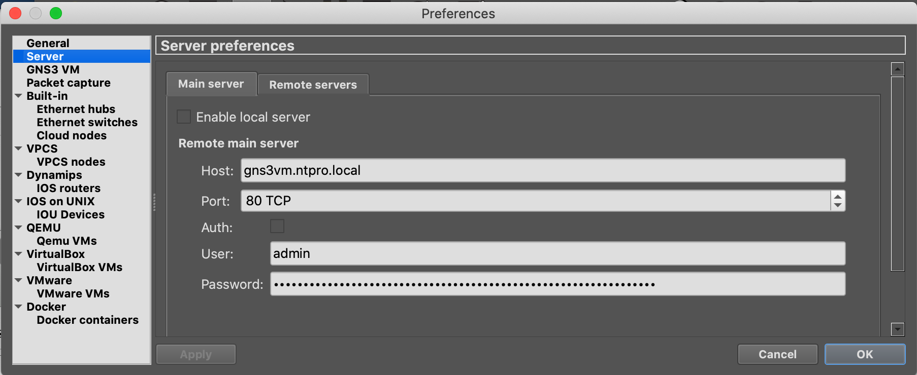
The client interface is configured with the fully qualified domain name of the GNS3-VM and port 80 instead of the default 3080.
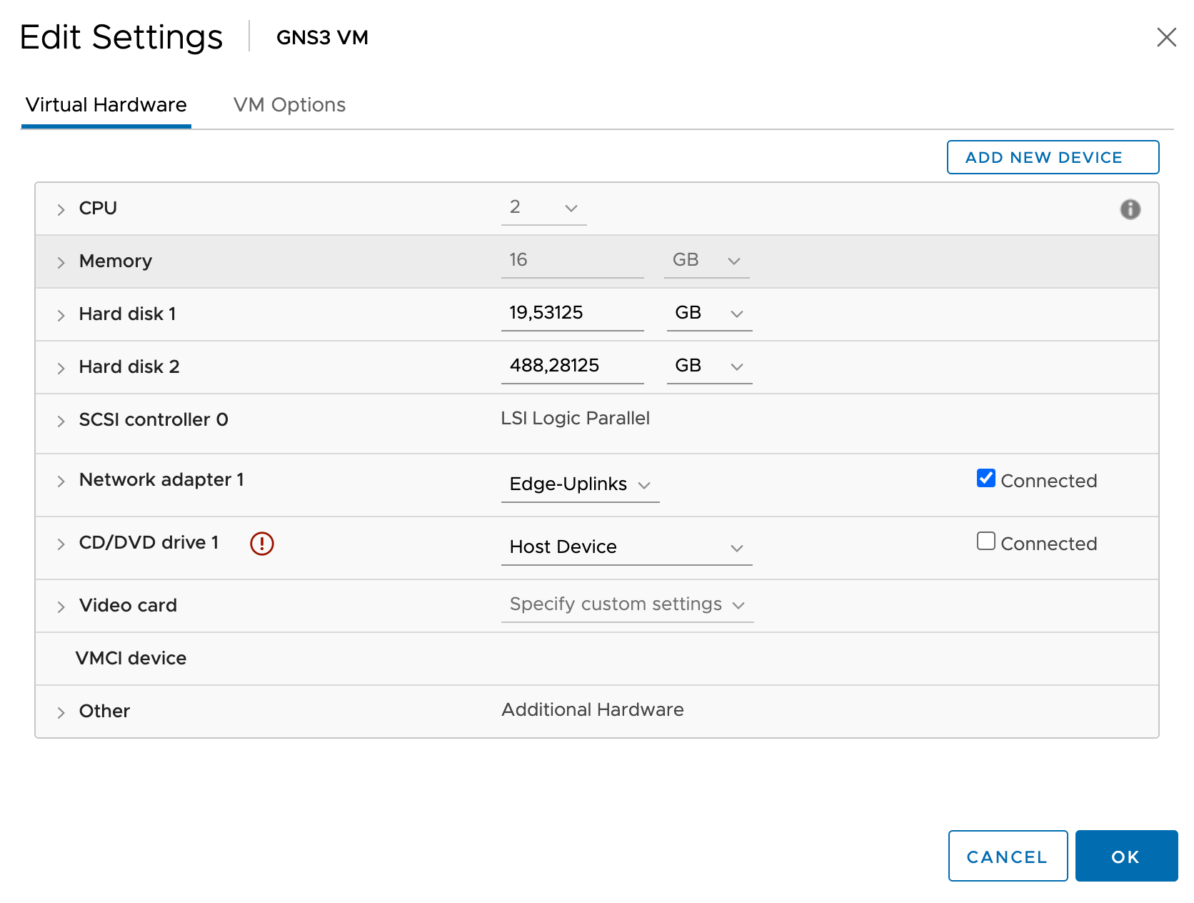
I also changed some settings of the GNS3-VM and configured an additional vCPU and a bit more memory. There's one other thing you need to do and that's removing one network adaptor.
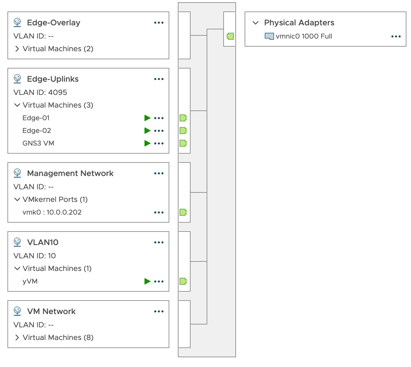
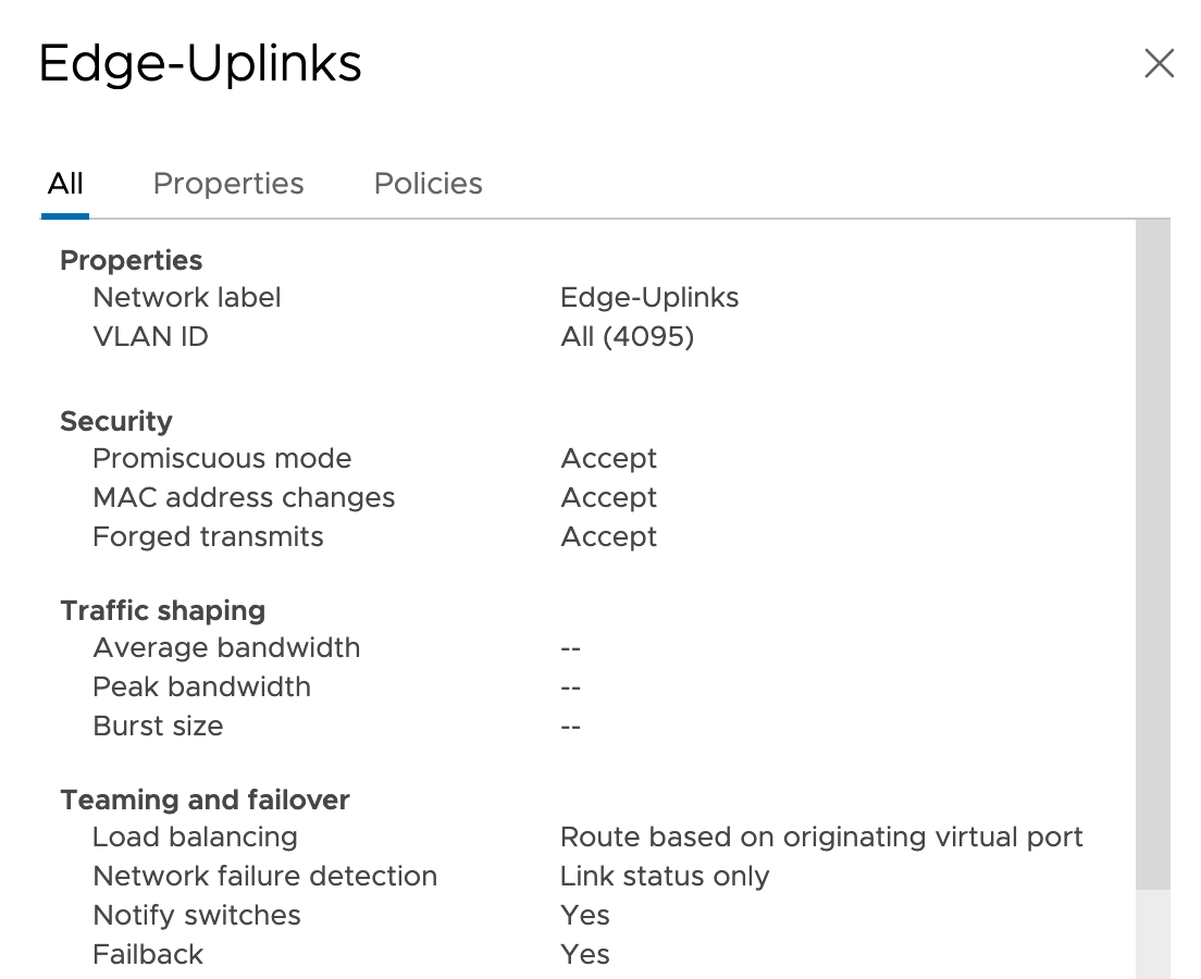
So I have One network adaptor that's attached to a port group configured in trunk mode (Edge-Uplinks). This adaptor must be able to forward tagged traffic from the cloud component so we have to install the Ubuntu VLAN kernel module.
Taken from: Enabling 802.1q on the GNS3 VM
First, install VLANs on the GNS3 VM:
sudo apt-get install vlan
Load 802.1q into the kernel:
sudo modprobe 8021q
To load it permanently so it survives reloads of the VM:
sudo su -c 'echo "8021q" >> /etc/modules'
Make sure that the security settings on this port group are all enabled. So Promiscuous mode, MAC address changes, and Forged transmits must be enabled.
I've also deployed a yVM (An ultra-small VM with VM tools) and attached it to a port group configured with VLAN 10. The IP address of this yVM is 172.16.10.20.
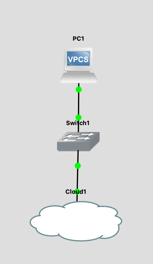
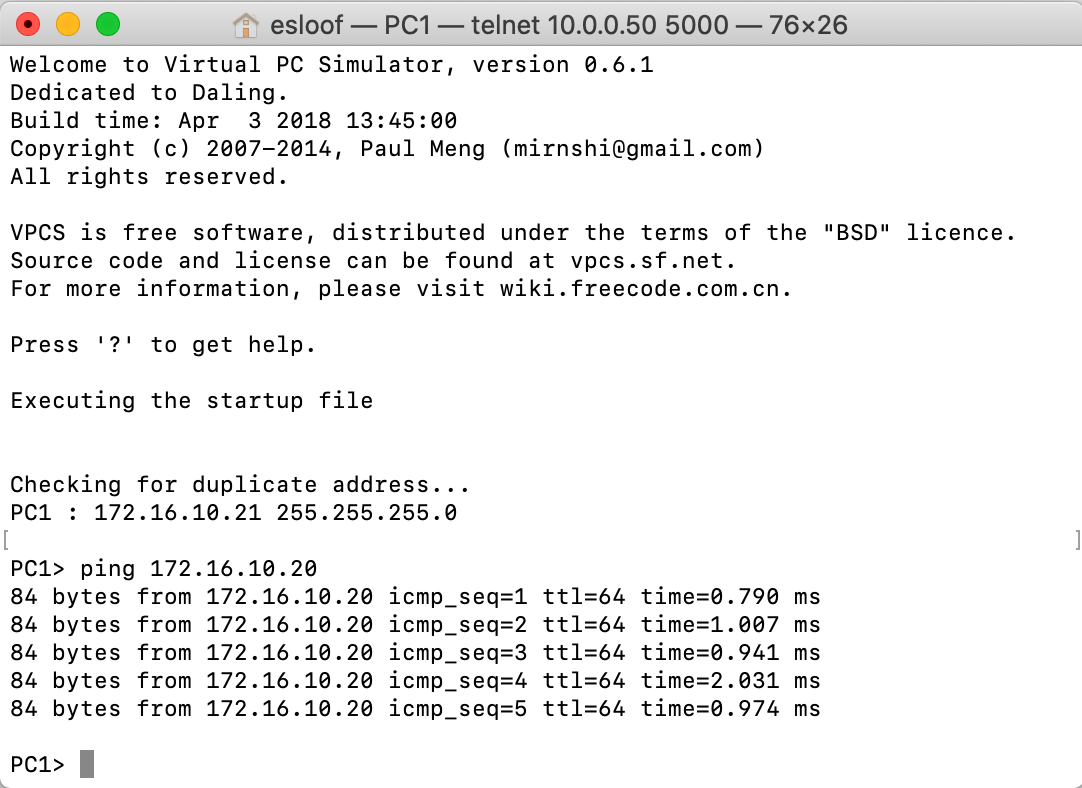
On the other side, The cloud component is connected to the virtual network adaptor of my GNS3-VM and attached it to a GNS3 ethernet switch "Switch1". The switch is connected to a virtual PC with IP address 172.16.10.21.
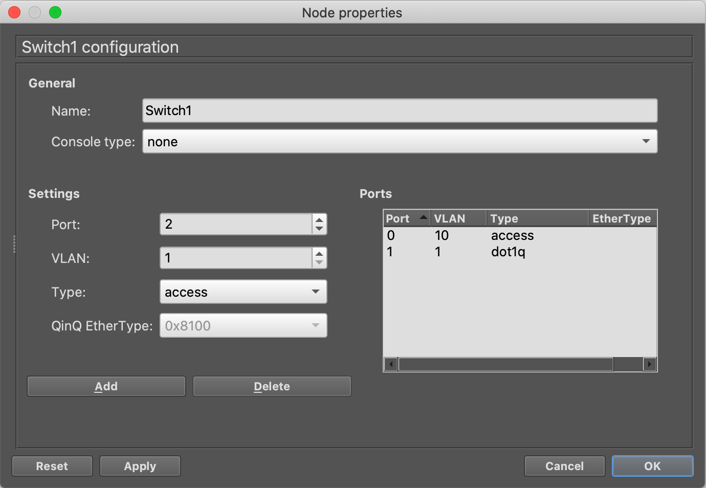
The switch is configured with a trunk (dot1q) downlink to the cloud component, the uplink is configured as a VLAN access port with ID 10.
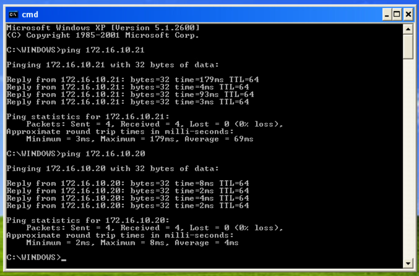
The VLAN that's configured on the dot1q (IEEE 802.1Q) port is the VLAN that's NOT forwarded to the cloud component. So if you put 10 in here it doesn't work. That's why you see 1 which is the default (unused) VLAN on this trunk. Now I must be able to ping from the vPC to the yVM.
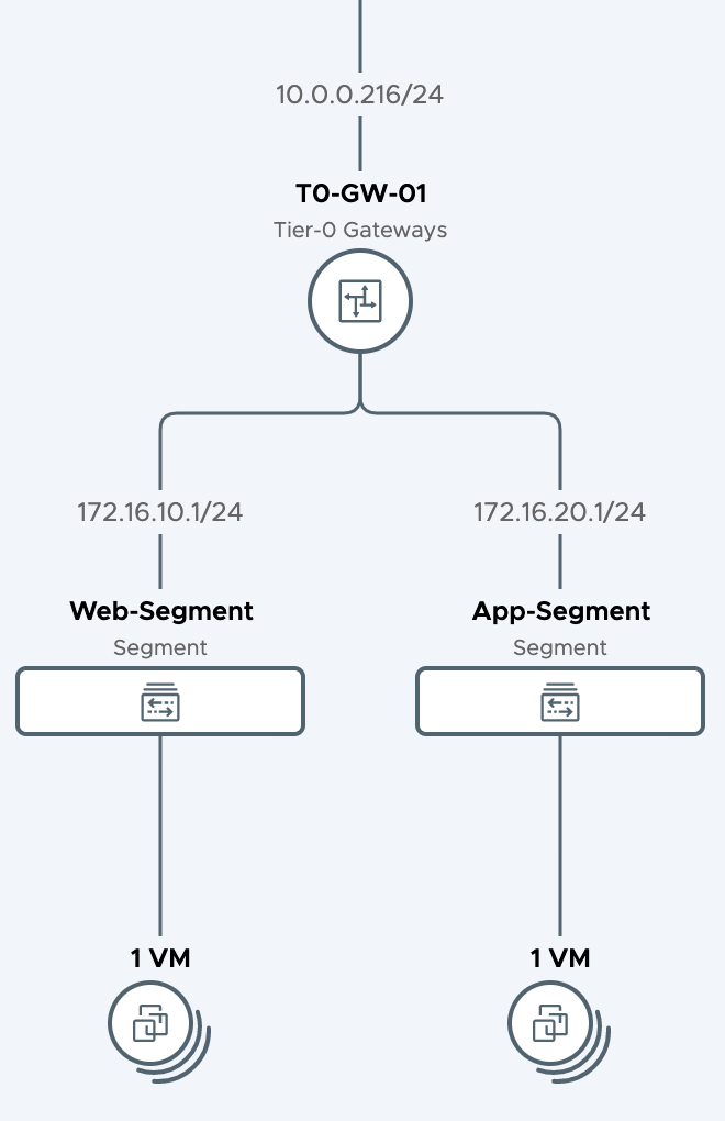
So it works :-) but let's take it one step further and add-in some NSX-T 3.0 magic. In NSX-T I've attached a Web segment to a T0 gateway. The edge service router VM is attached to the Edge-Uplink port group configured in trunk mode.
The segment is configured with a gateway address 172.16.10.1 and it's attached to a TO gateway.
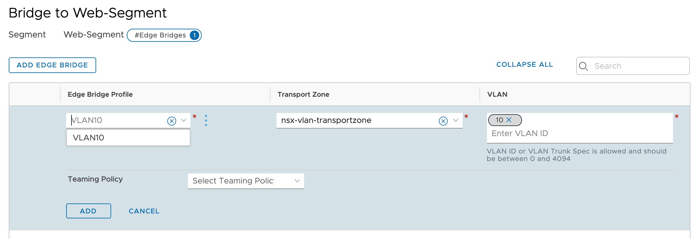
The web segment is also attached to an Edge Bridge Profile configured with VLAN ID 10.
So now we have a bridged network between VLAN ID 10 from GNS3, VLAN ID 10 from the yVM port group, and the Web Segment. I should be able to ping from the Web-VM that's attached to the Web-Segment to the vPC and the yVM.
The virtual machine that's attached to the Web-Segment is configured with IP address 172.16.10.12.
As you can see I'm able to ping from the Web VM to the yVM and the vPC.
