This article describes how to hook-up a Cisco C3745 router hosted on GNS3 to a T0 router hosted on VMware NSX and create a BGP Neighbor Adjacency between them. In my home lab, I'm running GNS 3 on an iMac. There is a special component available that allows you to connect the GNS3 world to the physical world. This cloud component can be attached to an extra network interface of your GNS3 VM.
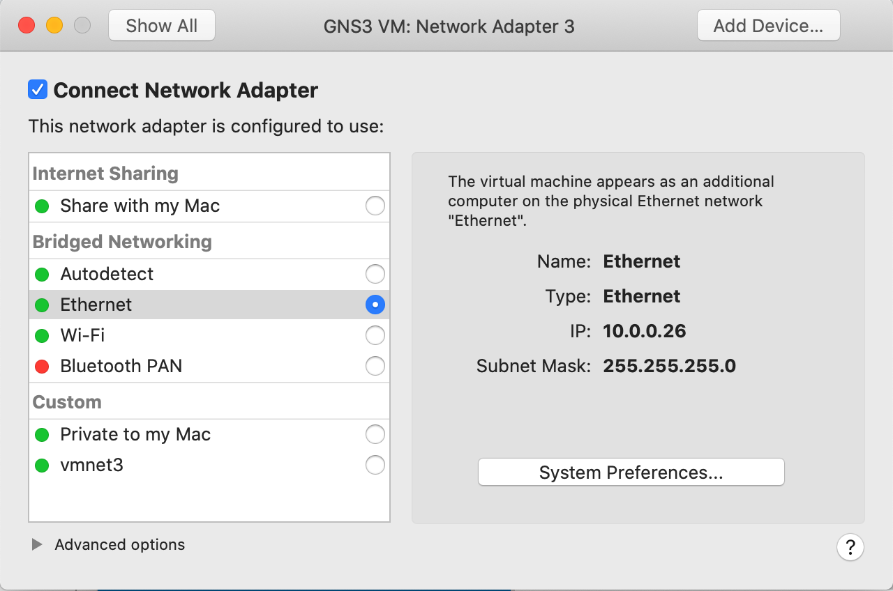
In this picture, I've added a third network adapter to my GNS3 Fusion VM. This adapter is connected to my physical network 10.0.0.0/24.
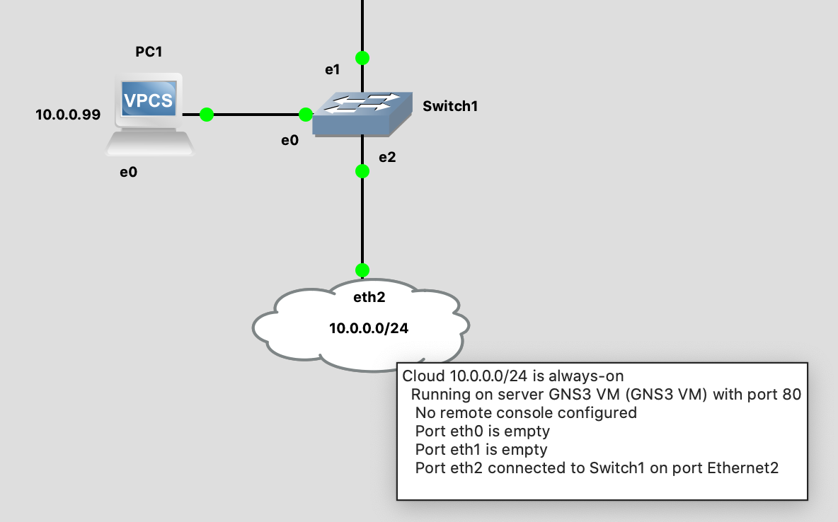
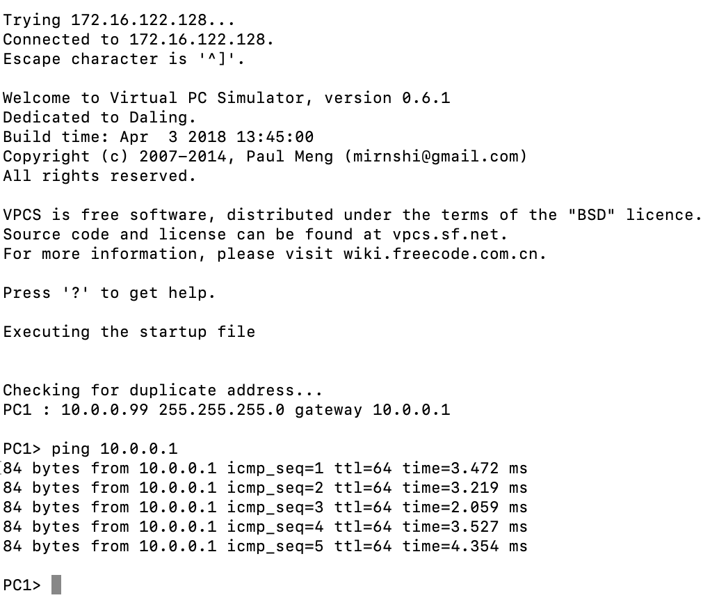
In GNS3 I've dragged the cloud component into the canvas and attached it to eth2. This eth2 port is mapped network adapter 3 of my GNS3 VM. I also dragged a switch and a virtual PC into the canvas, and attached the vPC and cloud component to the switch. I can now ping from the virtual PC to the default gateway of my home network.
On the other side, I'm running VMware NSX on a Supermicro 7047A-TB tower. I've created two segments and attached both segments to a T0 router. The two segments are configured with a gateway on 172.16.10.1 and 172.16.20.1. I'm hosting two servers, both servers are attached to their own segment.
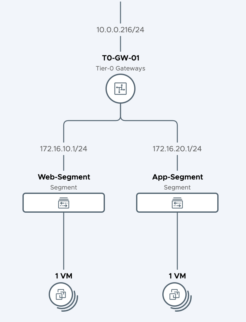
The Web and App server virtual machines are configured with 172.16.10.10 and 172.16.20.10. The uplink interface of the T0 router is configured with IP address 10.0.0.216.
My GNS3 project also hosts a virtual machine, this vPC is connected to a router. The Cisco C3745 router is connected to the switch, and the switch is connected to the cloud. The cloud component is connected to the physical network. My next goal was to set up a BGP Neighbor Adjacency between the Cisco C3745 router and the T0 router.
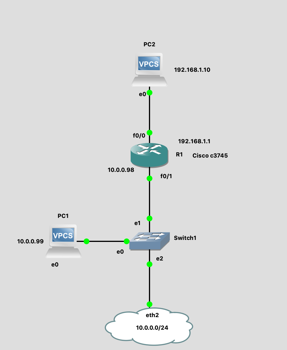
The PC2 vPC is configured with 192.168.1.10 and is connected to the gateway 192.168.1.1 on the Cisco c3745 router. The downlink of the router is configured with 10.0.0.98. I want to ping from the vPC to the web server virtual machine hosted in my VMware environment. The routes on the c3745 and T0 router must be exchanged with eBGP.
The first thing you need to do is upload the c3745 image into the GNS3 VM. The next step is to drag it into the canvas and configure the interfaces and BGP via the console. I'm not a real Cisco guy (correct me if I did it wrong ;-) but after some googling, I was able to configure the FastEthernet interfaces and BGP with the following commands:
enable
configure terminal
interface FastEthernet 0/0
ip address 192.168.1.1 255.255.255.0
no shutdown
^Z
configure terminal
interface FastEthernet 0/1
ip address 10.0.0.98 255.255.255.0
no shutdown
^Z
configure terminal
router bgp 64496
neighbor 10.0.0.216 remote-as 64497
address-family ipv4 unicast
network 192.168.1.0 mask 255.255.255.0
exit
exit
exit
wr
On the other side, I also had to configure BGP on the NSX-T T0 router. This can be done through the VMware NSX Policy UI instead of the console. The Cisco router is configured with autonomous system number 64496 and the T0 router is configured with AS 64497.


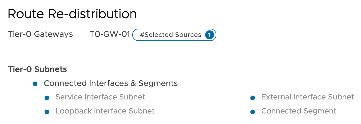
You also need to configure route redistribution and tell which routes are allowed to be announced through BGP.
When I putty into the NSX-T Edge VM and jump into the tier0_sr VRF, I should see if the BGP Neighbor Adjacency between the two routers was successfully established.
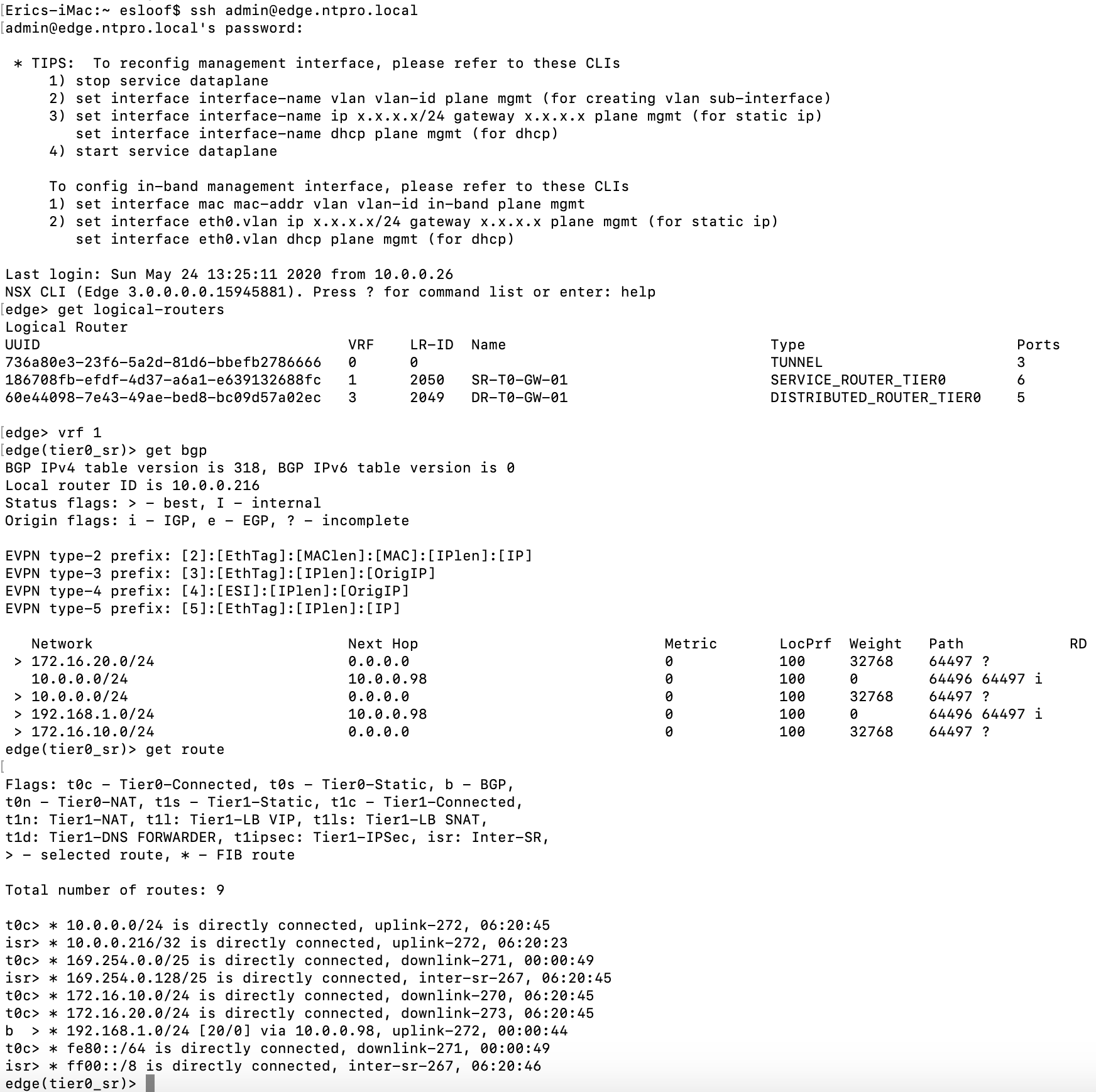
As you can see, I have established a neighbor relationship with the Cisco router, and I've learned that the 192.168.1.0 network can be reached through 10.0.0.98. On the other side, I can also check the BGP adjacency on the Cisco router.
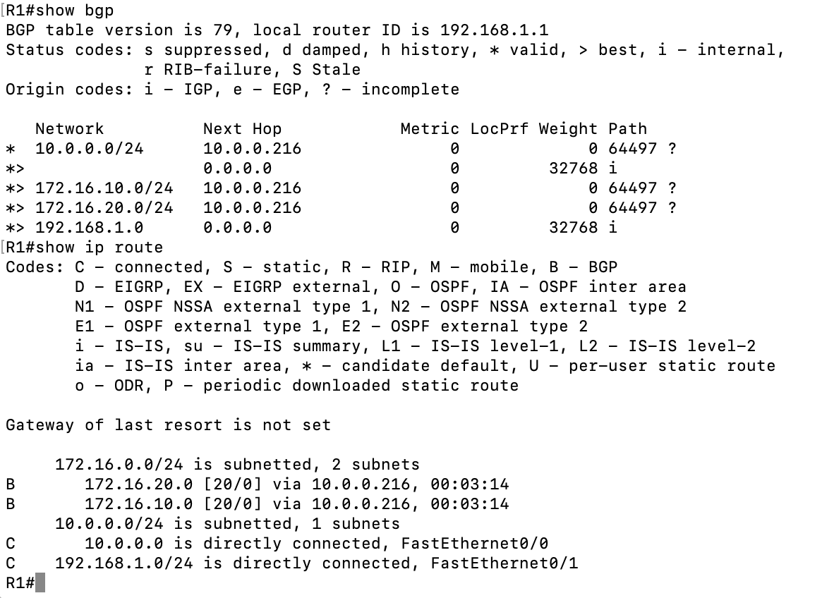
We can clearly see that the BGP adjacency was successful, and we can route both 172.16 networks through 10.0.0.216. The proof is in the pudding, so let's try to ping from the vPC to the Web server.
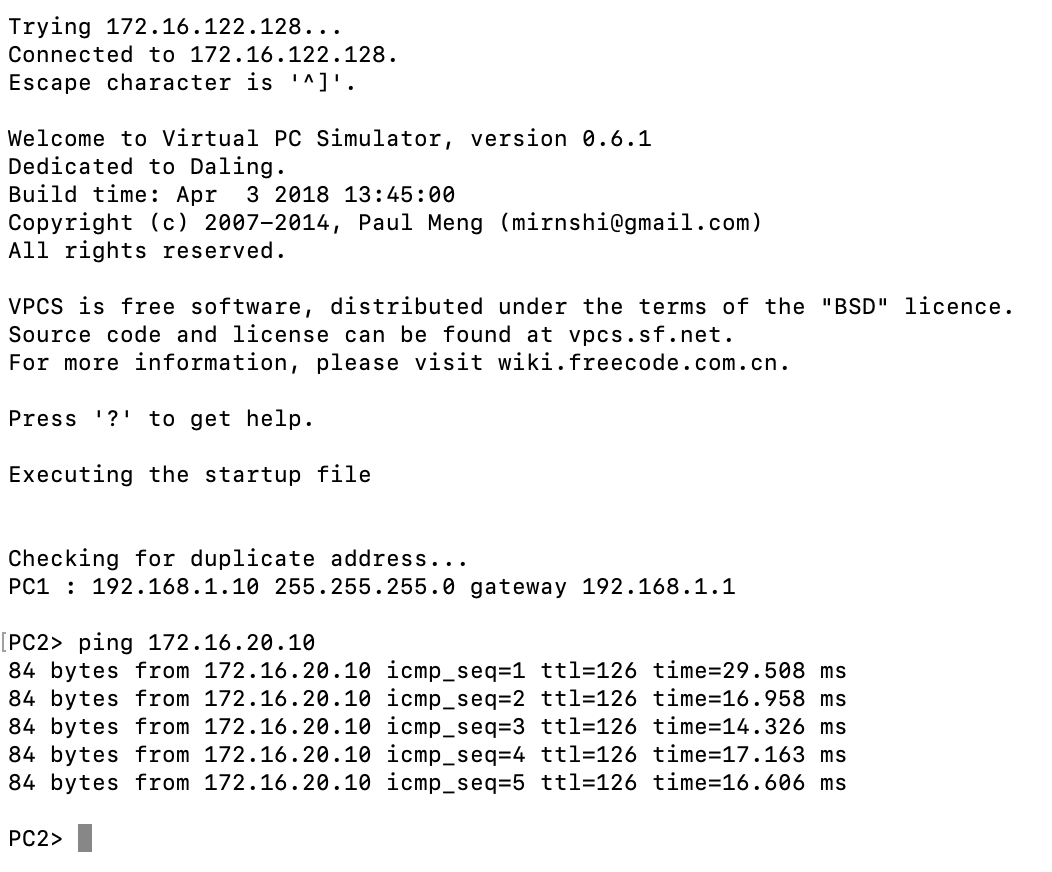
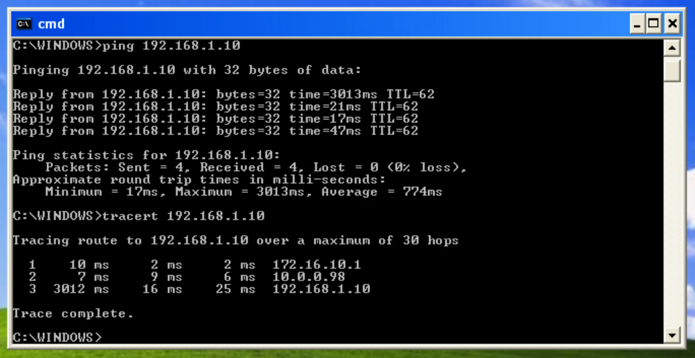
And yes, the ping runs successfully. To make it complete, let's do a trace-route from the App server to the vPC.
