Part 1 – The setup
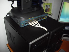
This week I’ve received a test model of the Cisco Catalyst 2960G-8TC-L from the nice people over at Azlan, the Enterprise Division of Tech Data Corporation. The switch has 8 Ethernet 10/100/1000 ports, one of which is for dual-purpose, besides that it’s very compact in size with no fan. The 2960G-8TC-L is also fully compatible with the Catalyst series and has a LAN Based Image installed, the ideal switch for your home lab. I’m going to write a couple of articles about how to configure trunking between a Cisco Catalyst switch and a VMware distributed virtual switch.
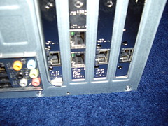
First let’s start with the lab-setup, my home lab consists of two Asus barebones, both with 8 GB memory, some local 500 GB SATA disks and two Quad CPU Q9400 CPUs. For shared storage I’m using the Iomega StorCenter ix2 (Chad ;-) I’m still waiting for the ix4). I’ve bought a couple of Intel PRO/1000 GT single port network cards and have placed them in every free slot I could find in the barebones. This leaves me with 4 network cards per server, enough to setup a nice network test environment.
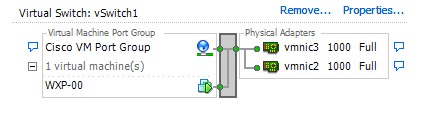
On my ESX server I’ve created a single standard virtual switch with two NICs which are connected to the Cisco switch. One Windows XP virtual machine with DHCP enabled. The VM is connected to the newly created Cisco VM Port Group. I’m going to use this virtual machine to do the initial configuration of the 2960.
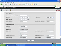
The following step is taken from the Cisco’s getting started guide. When you first set up the switch, you should use Express Setup to enter the initial IP information. This enables the switch to connect to local routers and the Internet. You can then access the switch through the IP address for further configuration.
When the switch power is on, it begins the power-on self-test (POST). During POST, the LEDs blink while tests verify that the switch functions properly. Wait for the switch to complete POST, which can take several minutes.
Press and hold the Mode button for 3 seconds. When all of the LEDs left of the Mode button turn green, release the Mode button. If the LEDs left of the Mode button begin to blink, after you press the button, release it. Blinking LEDs mean that the switch has already been configured and cannot go into Express Setup mode. During Express Setup, the switch acts as a DHCP server. If your PC has a static IP address, change your PC settings before you begin to temporarily use DHCP.
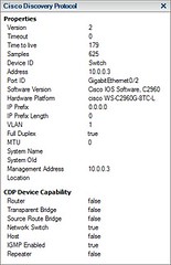
Now I’m logged on to the console of the VM and I opened up the Internet Explorer. When I’m looking at the Cisco Discovery Protocol information, I can see that the IP address of the switch is 10.0.0.3. I’ve pointed the browser to that address to provide the switch with its final IP address.
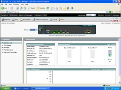
The switch is configured with IP address 172.16.1.1. The VM is able to log on to the newly configured address and I’ve gained access to the Catalyst 2960 Series Device Manager.